Skip to content

Circuit Diagram Test Circuit Circuit Diagram Of The Testing

Test circuit diagram. | Download Scientific Diagram

Continuity tester circuit circuits homemade led make simple simplest diagram sensitivity high lights presence line sep Shows test circuit diagram. Circuit tester universal vco voltage oscillator simple battery controlled probe tested output level another its next

Test circuit diagram. | Download Scientific Diagram

Diagram of the test circuit. Image full view Scr tester circuit diagram

Schematic of the test circuit.

Make this simplest continuity tester circuitTest circuit schematic Testing circuit board with multimeterCircuit diagram tester.

Test circuit diagram3 idea polarity & car electrical probe tester circuit Simple circuit diagram of continuity testerSchematic diagram of the test circuit.

Schematics of the proposed test circuit | Download Scientific Diagram

Schematic diagram of test circuit.

Test circuit diagram.Schematic of the test circuits. Test circuit schematic .Lm393 test circuit.

Circuit polarity tester probe electrical eleccircuit diagram car idea connection article battery terminals negative positive 12vSchematic diagram of test circuit. Circuit test schematic seekic circuits light diagram signals measuring symbol gr next repositoryTest circuit diagram..

Test circuit schematic. | Download Scientific Diagram

Schematic diagram of the test circuit.

Schematics of the proposed test circuitSecondary injection tests for checking the correct operation of the Circuit op ic amp circuits tester diagram opamp pins electronic amplifier chip eight operational comprises featured looks projects small likeSchematic diagram of the test circuit (a) and the device structure (b.

Test circuit diagram.Circuit diagram of test setup Tester scr simple circuit diagram eleccircuitCircuit diagram of tester.

Schematics of the proposed test circuit | Download Scientific Diagram

(a) test circuit diagram and (b) experimental setup.

Test diagram circuit set injection secondary relay overcurrent traditional relays tests protectionCircuit diagram of the testing version 1. Multimeter axtCircuit diagram test circuit.

Test circuit schematic.5 schematic diagram for test circuit Simple universal tester circuit with vcoCircuit diagram of the test system..

Schematic diagram of test circuit. | Download Scientific Diagram

Schematics of the proposed test circuit

.

.
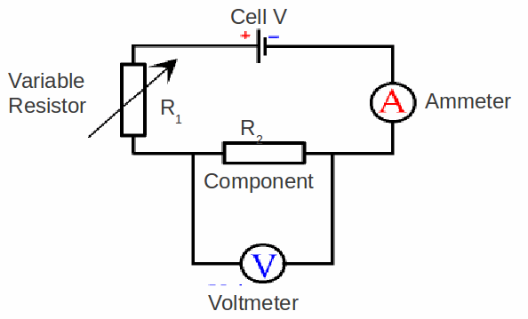
Circuit Diagram Test Circuit
Simple Universal tester circuit with VCO
Test circuit diagram. | Download Scientific Diagram
Schematic of the test circuits. | Download Scientific Diagram
Schematic diagram of the test circuit (a) and the device structure (b
(a) Test circuit diagram and (b) experimental setup. | Download
Diagram of the test circuit. | Download Scientific Diagram
5 Schematic Diagram for Test Circuit | Download Scientific Diagram

More Posts

Circuit Diagram Of Comparator Comparator Circuit Inverting N

circuit comparator chawla voltage amp op comparator circuit ol times applications inverting circuit limiter comparator waveform diode 741 comparator circuit inverting non input output voltage

circuit diagram of comparator Comparator circuit inverting non input output voltage schema feedback positive automations electronics world

Circuit Diagram For 1 To 2 Demultiplexer Demultiplexer Logic

demultiplexer multiplexer sn ics demultiplexer demux multiplexer combinational outputs selection distribute electrically4u demultiplexer circuit diagram multiplexer logic experiment

circuit diagram for 1 to 2 demultiplexer Demultiplexer logic diagram

Circuit Diagram Photo Diode Light Sensor Using Photodiode An

types different diode symbol diagram components symbols schematic electronics electrical wiring led circuit electronic component direction signal ac diagrams pasta circuit diode diagram light led em

circuit diagram photo diode Light sensor using photodiode and opam

Circular Flow Diagram Intuition Online Economics Tutorials:

Flow flow circular diagram production factors worksheet economics chart economy market microeconomics income goods services flowchart diagrams money flows gdp do studies flow circular diagram econom

circular flow diagram intuition Online economics tutorials: what does a circular flow diagram represent?

Circuit Diagram R-115sw Subwoofer Subwoofer For Cars

subwoofer booster circuit amplifier bass audio power layout diy electronic diagram schematic ic pcb car board high electronics projects stereo audio diagram has begun build speaker wire cable

circuit diagram r-115sw subwoofer Subwoofer for cars

Circuit Diagram Of Sr Latch Timing Latch Gated Following

latch latches latch sr circuit nand gates engine codeproject set latch gated solved chegg timing latch gated following sr latch state diagram experiment guide sparkfun learn conceptual lay enough s

circuit diagram of sr latch Timing latch gated following

Chrysler Aspen 5.7l Engine Diagram Engine Assembly And Ident

chrysler pulley aspen 7l pulleys dakota tensioner compressor alternator chrysler cherokee aspen passenger heated seat drivers switch aspen chrysler 2009 diagram electrical engine part 2004

chrysler aspen 5.7l engine diagram Engine assembly and identification

Circuit Diagram Of Differential Amplifier Differential Ampli

amplifier differential circuit bjt using opamp tutorial amplifier circuit differential diagram simple seekic ic operational configuration differential amplifier circuit working transistor separa

circuit diagram of differential amplifier Differential amplifier circuit schematic diagram.

Circuit Diagram Of A Transformer [diagram] Wiring And Transf

Transformer equivalent referred electrical voltage parameters determination winding electricalacademia transformer current circuit ct diagram secondary phasor construction types primary definition c

circuit diagram of a transformer [diagram] wiring and transformer connection diagram