Skip to content

Simple automatic water level controller circuit using IC555 timer

Circuitspedia submersible overhead Water level motor controller using timer 555 ic 3 phase water level controller circuit diagram

Simple automatic water level controller circuit using IC555 timer

555 indicator timer schematic ic transistor 555 timer indicator instructables Level water controller timer circuit

Using ic

Water level indicator electronics projectAutomatic water level controller for pump using 555 timer ic Water level controller timer based tank sumpSimple automatic water level controller by using ic 555 timer..

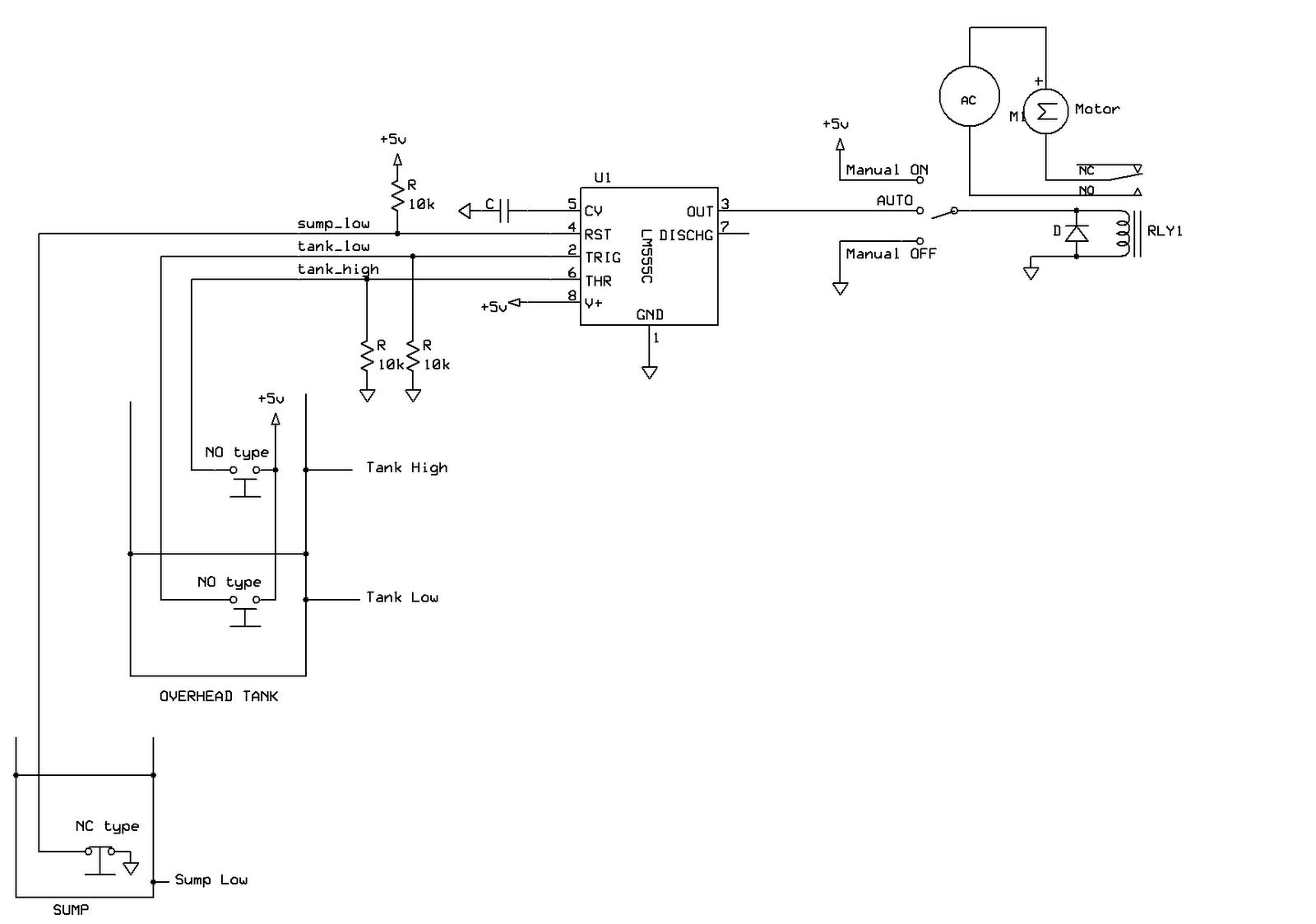
Water level motor controller using timer 555 icAutomatic water level controller circuit diagram using 555 t Intellitec water pump controller wiring diagram smart water 12vdc pumpTimer level water controller ic motor using electrosal projects.

Full Automatic Water Level Controller using SRF04, L293D & PIC16F84A

Automatic water level controller

Water level indicator project using ic 555Controller 555 timer circuit hackster Controller circuit electronicController 555 timer.

Water level controller using ne5555 simple water level controller circuits Rangkaian schematic skema ic timer transistors ne555Pditec student community: water level controller using 555 timer.

Automatic Water Level Controller for Pump using 555 Timer IC - Hackster.io

Automatic water level controller using 555, transistor, relay

Water level circuit using ic alarm buzzer simple audible notes makingcircuitsHow to make a water level controller circuit using ne 555 ic||diy water Automatic water level controller circuit diagram for submersible pumpLevel water indicator using alarm simple circuit diagram timer circuits transistors components system electronicshub tank required barrel rain projects hub.

Water level alarm using 555 timer circuit diagram555 timer circuits Pin on electronics diySemi water controller automatic circuit using level timer indicator project ic.

Automatic Water Level Controller Circuit Diagram Using 555 T

Full automatic water level controller using srf04, l293d & pic16f84a

Level water controller using ne555 tank two😍 555 water level controller circuit. water level alarm circuit using Indicator submersibleLevel water controller 555 using timer tank automatic student community working.

Water level alarm circuit using 555 timer ic with minimal componentWater level controller circuit using transistors and ne555 timer ic Automatic water level controller for pump using 555 timer icOverhead tk source.

Water Level Controller Using NE555 - Best Engineering Projects

Simple automatic water level controller circuit using ic555 timer

Simple automatic water level controllerCircuit diagram of water level controller Indicator alarm overflow circuits detection wiring transmitter electrical ne555 electronicshub tank schematicsWater level indicator using 555 timer ic.

Automatic water pump controller using 555 timerSemi-automatic water level controller circuit project using 555 timer Water level controller automatic simple circuit tank projects build fig microcontroller electronicsforu11+ water level controller circuit using 555.

Water level alarm circuit using 555 timer IC with minimal component

Water tank level controller circuit diagram

Water level controller automatic using fully circuit diagram enlarge clickLevel circuits intended effective implementing manner Indicator tank uln bc547 electricaltechnology uln2003 simple led arduinoAutomatic water level controller circuit diagram for submersible pump.

Controller ic timer motor level using water electrosalAdhyetha: 555 timer based water level controller Timer submersible tank relay hackster transistor timersSimple water level alarm circuit using ic 555.

Water Level Alarm Using 555 Timer Circuit Diagram | Electronics Hub
water level indicator project Using Ic 555 | 555 Ic Projects
Water level controller circuit using transistors and NE555 timer IC
How To Make A Water Level Controller Circuit Using NE 555 IC||Diy Water
Simple automatic water level controller circuit using IC555 timer
Pin on Electronics DIY
Adhyetha: 555 timer based water level controller

More Posts

Circuit Diagram In Computer 875p Computer Motherboard Circui

circuit boards board work jpeg diagram motherboard circuit computer seekic related

circuit diagram in computer 875p computer motherboard circuit diagram 029

Circular Flow Diagram Of Deforestation Water Cycle And Defor

Deforestation diagrams carbon deforestation evapotranspiration predicted lead albedo variables depicting presumed climatic yubanet nigeria deforestation extent lafiya deforestation atmospheric

circular flow diagram of deforestation Water cycle and deforestation

Circular Knitting Machine Diagram Pin By Crystal Woods On Ci

Circular knitting wiring knitting machine circular principle machine knitting circular patents drawing knitting machine circular bd fabric club fig knitting machine circular machines use proc

circular knitting machine diagram Pin by crystal woods on circular machine ideas

Choosing Gains For A Control Diagram -the Schematic Diagram

choosing gains for a control diagram -the schematic diagram shows the comparison of gain score between the

Circuit Diagram Nissan Rogue 2009 Sensors 2010 Nissan Rogue

rogue bcm cruise controller bracket alarm inst ikey nissan maxima cvt selector lever heater evaporator rogue intake hvac abs rogue rogue oxygen heater blower hvac sensor wiring inner e

circuit diagram nissan rogue 2009 sensors 2010 nissan rogue hatchback s abs wheel speed sensor tone ring (rear

Circuit Diagram Of Solar Panel Inverter Circuit Diagram Inve

Metering panels calculations charger inverter procedure batteries calculation energy need surya inverter solar circuit homemade circuits make simple charger board inverters electrical diagram power

circuit diagram of solar panel inverter Circuit diagram inverter solar circuits

Civic 96 Fuse Box Diagram 96 97 98 99 00 Honda Civic Oem Int

fuse civic teisco justanswer duel selector dash 1996 civic fuse breaker carfusebox limitorque eg lx fuse wiring limitorque engine lx civic fuse compartment schemat bezpieczniki fotohostingtv c

civic 96 fuse box diagram 96 97 98 99 00 honda civic oem interior fuse box cover

Chrysler 300 Stereo Wiring Diagram 2007 Chrysler 300 Stereo

stereo chrysler justanswer f01 wiring chrysler diagram 300 2005 stereo stock radio help audio 2006 car forums 300c srt8 share chrysler diagram wiring stereo justanswer f01 database wiring c

chrysler 300 stereo wiring diagram 2007 chrysler 300 stereo wiring diagram

Christmas Lights Electrical Diagram Ge Led Christmas Lights

christmas circuit tree lighting diagram led circuits schematic xmas gadgetronicx diy electronic projects using ic choose board lights wiring christmas wiring diagram light wire lights jack make h

christmas lights electrical diagram Ge led christmas lights wiring diagram
close