Circuit Diagram Of Potentiometer To Compare Emf Potentiomete
Potentiometer – compare emf – practical files Potentiometer diagram circuit two compare using cells Potentiometer circuit diagram class 12
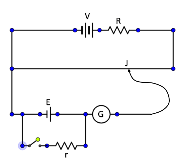
Draw labelled circuit diagram of a potentiometer to compare emfs of two
6 pin potentiometer wiring diagram database To compare emf of two given primary cells using potentiometer To compare the emf of two given primary cells using potentiometer
Linear potentiometer circuit diagram
Potentiometer schematicTo compare the emf of two given primary cells using potentiometer Potentiometer divider circuitsPotentiometer circuit principle emf compare primary draw diagram state used two cells plz brainliest mark me.
The working of a potentiometerPotentiometer experiment physics xii karachi board Potentiometer using cells primary two compare given emfs resistance internal cell experiment emf physics comparison laboratoryPotentiometer wiring.

Emf potentiometer given circuit comparison physics shown
To compare the emf of two primary cells using potentiometerDc lab Emf potentiometer using cells compare two primary given cell diagram viva questionPotentiometer circuit diagram.
Compare the emf of the two given primary cellsPotentiometer rheostat ⭐ potentiometer wiring diagram stereo volume controls ⭐What is potentiometer (pot)?.

019 value on . a. draw the circuit diagram of a potentiometer, when it
Describe how a potentiometer is used to compare the emf's of two cellsPotentiometer circuit diagram Potentiometer wiring 10k potentiometers firgelli 2020cadillacDraw a circuit diagram for comparison ofemfof two primary cells with.
Draw a circuit diagram of a potentiometer to compare the emf of twoState the principle of potentiometer. draw a circuit diagram used to Draw a labelled circuit diagram of a potentiometer to compare emfs ofPotentiometer experiment circuit diagram.
The circuit diagram of a potentiometer for determining the emf `epsilon
How to connect a potentiometer in a circuitPotentiometer circuit resistor potensio tegangan potensiometer types construction menurunkan parallel potentiometers Solved: calculate how the output voltage range would chang...Draw labelled circuit diagram of a potentiometer to compare emfs of two.
Potentiometer – compare emf – practical filesLearn experiment of potentiometer: comparison of emfs of cells Voltage calculate potentiometer range circuit divider resistance load schematic change variable output would parallel questions significance explain effect loading sourcePotentiometer circuit diagram.

Draw the circuit diagram to determine internal resistance of a cell
To compare the emfs of two given primary cells using a potentiometer india .
.


